277 Rotax - Rotax 277 Engine Manual
To avoid damage to the crankshaft resp. to the bearing, the puller
assy. for ball bearing 6305.has to be used (see removing of bearing, ill.
no. 6).
MOUNTING OF CRANKSHAFT
Warm crankcase, magneto side, up to approx. 800C
( 180 degrees F) Press oil seal 230 425 with mounting jig till to the stop.
Press
crankcase ring 960 765 in with mounting jig.
Fill groove between oil seal
lips with high temperature bearing grease and mount crankshaft.
Place
crankcase gasket.
Mount oil seal 850 050 and aluminum crankcase ring 827 820 in
crankcase, p.t.o. side.
Mount crankcase half.
Tool: Rubber hammer (plastic hammer).
Tighten hex. screws of crankcase in a cross sequence (starting from the middle) with 18
-24 Nm (160-210 in.lbs)
Tools:
Torque wrench insert 13 for torque wrench
Close crankcase cavity with a clean cloth.
Insert piston pin needle cages in bore of connecting rod
Warm up piston to 40 - 50 degrees c
(arrow on top of piston must show
towards exhaust).
Insert guide pin for piston pin through the piston hole and connecting
rod bore. Take care not to damage the needle bearing.
Coat piston pin with oil, place it on guide pin and insert it
into piston hole. All punch impact must be absorbed by your hand to avoid
bending of the rod (arrow on piston crown must show towards exhaust).
Secure pist0n pin with circlips. ATTENTION:
The circlips must engage in the grooves of the piston. Use new
circlips. Insert circlip, in such a way that open ends are not over the
rectangular slot of the piston, as otherwise the circlip would have to be turned around when
disassembling
later on.
Circlips must sit tightly in the groove.
Tool: Screwdriver shaped as shown on ill. no. 2
Mount cylinder base gasket.
Attention: This gasket is
not symmetrical. Place it in the correct position. Take care of the transfer recesses in the
crankcase.
Lubricate piston and bring piston rings in correct position (securing
pin between ends of piston ring).
Press piston rings into the grooves and mount oiled cylinder over the
piston.
Mount cylinder head gasket and cylinder head. Tighten hex. nuts M8 at
18 - 24 Nn (160 - 210 in. lbs) in a cross sequence,
Tools: Torque wrench insert 13 nun for torque wrench.
Mount armature plate so that marks on armature plate and crankcase
correspond.
Fix armature plate with allen head screws and insert cable grommet.
Tool: Hex. socket screw key 4 mm
Mount Woodruff key on crankshaft taper.
Fix piston to top dead center by inserting a crankshaft fixation bolt
through the impulse nipple.
277 Rotax - Rotax 277 Engine Manual
Clean crankshaft taper and taper in inagneto housing with degreasing
agent (e.g. trichloroethylene).
Coat crankshaft taper with LOCTITE 242 blue (899 786)
Mount magneto housing with assembled fan on the
crank shaft.
Attention:
Before mounting magneto housing with fan on the crank- shaft, take care
that the ignition unit and especially the magnets are clean and free of
foreign material.
Magneto housing nut
Secure thread of hex. nut M18 x 1.5 with LOCTITE 242 blue,
899 786, and tighten hex. nut with torque 90 Nm (800
in. lbs).
Tools:
Torque wrench insert 27 mm for torque wrench
IGNITION ADJUSTMENT
Ignition timing 190 ( 2.03 - 2.53 mm
or 0.08 - 0.10 in before top dead center)
Procedure
To adjust the contact breaker gap., the piston has to be placed to top
dead center. Adjust contact breaker gap to 0.4 mm (0.016 in.). To do so,
loosen the fixation screws of the contact breaker set and push the
contacts with a screwdriver until the gap is 0.4 mm (0.016 in.). This
distance has to be checked with a feeler gauge.
Then turn crankshaft until the contact breaker cam makes the contact
lever lift (check with buzzer or check lamp); connection to shorting cable
and to mass.
Now the mark on crankcase has to correspond with the mark @ on the fan.
If the marks don't correspond, the contact breaker gap can vary between
0.35 and 0.45 MM (o.o14 -0.018 in.) to achieve correspondence.
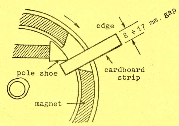
BREAK-AWAY GAP
When correct timing is achieved, check pole shoe break- away gap.' The
gap must be within 8 to 17 mm or 0.3 to 0.67 in. (see illustration) when the mark on the flywheel
corresponds with the mark on fan housing.
 If
the break-away gap is out of tolerance, the flywheel may have turned on
the crankshaft. Remove flywheel and inspect taper and key. Repair if
necessary. If
the break-away gap is out of tolerance, the flywheel may have turned on
the crankshaft. Remove flywheel and inspect taper and key. Repair if
necessary.
Mount ignition coil
Tools: Socket wrench 8 nun screwdriver
Screw on starting pulley
Tool: Socket wrench 10 mm
Mount fan cowl and cylinder cowl.
Tool: Socket wrench 10 and
13
mm
Mount carburetor socket with gasket
Tool: hex. socket screw key 6 mm 19 sp,
Screw on exhaust socket with gaskets and air guide.
Tool: hex. socket
screw key 6 mm.
Remove crankshaft fixation bolt.
|