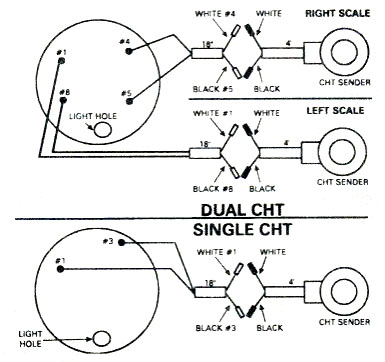
| A thermocouple is a device formed by the junction
between two special dissimilar metals which transforms heat energy into
electrical energy. Aviation EGT and some CHT systems use thermocouples,
lead wires composed of the same two dissimilar metals, and an gauge
which is basically a millivolt meter.
Most aviation EGT and CHT Systems are based around three
types or thermocouples. The most common type K, is used on most EGT
systems. It uses chromel and alumel wires in the element and lead. |
| Many CHT Systems use a type J system or iron
and constantan metals.
Thermocouples used in aviation are simple to
troubleshoot with a good quality digital multi-meter The meter should be
fitted with alligator clips on the test leads. |
Integrity check: Inspect the entire system
for loose connections, broken wires or connectors, or mismatched
color codes.
Color codes must match throughout the entire system
from the indicator to the probe, including the lead wires.
Resistance check: Care should be taken
to be sure the meter and or the probe have been un-hooked before
checking for loop resistance. A grounded type K probe Will normally show
from O.6 to 1.0 ohms. The same goes for type E or red and brown probes.
Type J CHT probes will show a reading of about 0.24 ohms. NOTE: Many CHT
Systems do not operate on the thermocouple principle. A CHT probe with
no color codes or only one wire works on resistance changes as opposed
to millivolt output. Consult the manufacturer for details.
CAUTION - voltage from a multi-meter can damage an EGT or CHT indicator.
Millivolt output check, (EGT ONLY): Using a propane
torch, carefully heat the tip of the probe until it glows cherry red. At
this point, the probe should put out between 20 and 30 millivolts.
CAUTION - Always wear gloves and have a fire extinguisher handy when
using an open flame.
If your probe passes these tests, check with the
manufacturer of your indicator for calibration or repair information.
|
EGT System Troubleshooting
Guide
|
| SYMPTOM |
POSSIBLE CAUSE |
SOLUTION |
SEE NOTE |
| No Indication |
Open Thermocouple |
Check Probe: Heat Resistance |
1 |
| Shorted or Open Circuit |
Check Continuity |
2 |
| C/A Probe on C/C System |
Check Color Codes |
3 |
| Bad Pot |
Repair
or Replace |
4 |
| Friction in Movement |
Repair
or Replace |
4 |
Low Indication
at Peak |
| C/A Probe on C/C System |
Check Color Codes |
3 |
| Probe - High Resistance |
Check Probe Heat or Resistance |
1 |
| High Indication |
| C/C Probe on C/A System |
Check Color Codes |
3 |
| Induced EMF Through Lead |
Check Harness Route |
5 |
| Erratic Reading |
Bad Potentiometer or
Friction in Movement |
Repair
or Replace |
4 |
T/C Wire Insulation
Worn at Radiator |
Check T/C Resistance While Wiggling Wire |
1 |
| Erratic Reading
at Altitude |
Lead Chafed-Grounding |
Check Continuity to Ground While in Fit |
2 |
| Indicator Change
when Tapped |
Faulty gauge |
Repair
or Replace |
4 |
| No Indicator
at Run-Up |
Indicator Begins at 1200 F
Not All Engines Reach
1200 F at Run-Up |
System Normal |
|
Indicator Works
on Bench,
Not in Flight |
Probe, leads |
Repair
or Replace |
4 |
|
|
1. The best way to troubleshoot EGT
probes is to check the loop resistance through the probe at room
temperature. Use a good quality multi-meter fitted with alligator clips
on the test leads.
CAUTION: Voltage from a multi-meter can damage an
EGT gauge.
Care should be taken to be sure the probe has been
disconnected from the system before checking for loop resistance. A
grounded red/yellow or red/brown probe will normally show from 0.6 to
1.0 ohms resistance.
To check millivolt output, remove probe from
aircraft. Carefully heat the tip of the probe element with a propane
torch until it just begins to glow dark cherry red. At this point, the
probe should put out from 33 to 36 millivolts (1500 to 1650 degrees F)
for red/yellow, or 61 to 67 millivolts (1500 to 1650 degrees F) for
red/brown.
CAUTION: Always wear gloves and have a fire extinguisher
handy when using an open flame. |
| 2. To check continuity of an EGT extension lead, first
inspect entire length of wire for chafing or broken insulation. Inspect
terminals for loose crimps or connections. With indicator and probe
disconnected, check to be sure that there is no continuity from red to
yellow or from red or yellow to thermocouple housing. Next, clip red to
yellow at either end and check for continuity at opposite end through
the entire lead. |
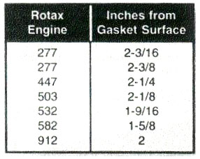
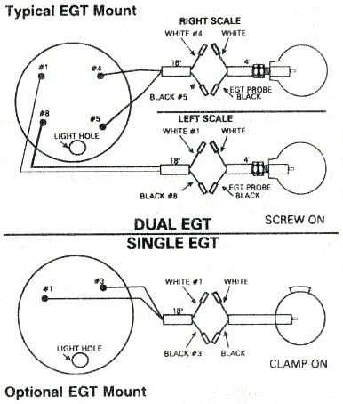
| 3. The latest Rotax engines use a bayonet style
probe, and the exhaust manifold has been manufactured for probe
placement at the correct distance from the piston.
Older units used a clamp on style probe which has to
be installed at the proper distance from the piston, has to be
centered on the manifold and in the exhaust pipe. It cannot be
allowed to touch the inside of the exhaust manifold pipe, it must
sit in the center of the exhaust gasses. |
4. Calibration on EGT or CHT indicators
MUST be checked against spark plug colour.
See How to read your spark plugs. |
| 5. To prevent indicator error due to induced EMF, the
EGT or CHT extension lead wires must not be bundled up or routed with
any high current bearing wires such as alternator, avionics, lighting,
heaters etc. |


